


Serial Data Link Emulator
High Speed Version
Features / Benefits
Serial Data Link Emulator * Interfaces - V.35, RS-530, RS-422/449, RS-232, X.21 or TTL * Network Simulation delays of 0, 5mS up to 1 second each direction * Data Rates - Synchronous 8kbps to 3.072Mbps * Controls for RTS/CTS delay, DSR, DTR on a per port basis * Status LEDs for each port allows ease of connection and trouble shooting * Timing - Internal or external depending on model ordered * 110/220VAC switch selectable * Sturdy Metal Enclosure
Description
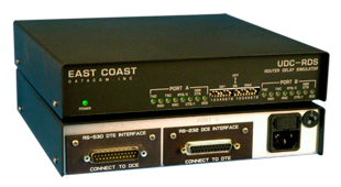
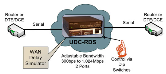
The UDC-RDS serial data link emulator allows users to test/stage critical low data rate testing of DCE or DTE equipment while emulating network delays. The unit provides a realistic simulation of physical network behavior with respect to time delays, clock rates and interface control signal passage. The unit supports user data rates of 8kbps up to 3.072Mbps while providing delays from zero to a maximum of 1 second on each way per physical data link.
By using the UDC-RDS in place of or in series with a real data link (WAN) a wide variety of error conditions can be introduced under controlled and testable conditions.
The unit has two data port interfaces that support RS-232, RS-422/449, RS-530, V.35 and X.21. The data interfaces can be mix and matched where applicable, such as a V.35-to-RS-530 connection.
The UDC-RDS also allows the user to pass or force control signals. The control signals are also delayed along with the user data.
The unit is configured via accessible front panel dip switches and is available in a stand-alone or rack mount chassis. The user has no software to load as all configuration is within the UDC-RDS. Installation is fast and simple by setting the internal switches for Delay Simulation, Clocking, Carrier Operation and RTS to CTS delay. All clocking and signal crossover are provided within the UDC-RDS.
The UDC-RDS has status LEDs for each attached DTE or DCE device which allows the user to visually confirm the presence of control signals.
The UDC-RDS is housed in a sturdy metal enclosure and operates on 110/220VAC.
The unit has a three year warranty and a 24 hour turnaround on warranty repairs.
SPECIFICATIONS |
|
| Application | Interconnection of two Routers or DTE (Terminal) devices located within proximity of each other while simulating network delays times |
| Simulation Delay Times | 0, 5 milliseconds(mS) to approximately 1 second in 5mS increments each direction Note: |
| Capacity |
Two (2) Routers or DTEs /DCEs |
| Data Rates | 8kbps to 3.072Mbps |
| Data Channel Interfaces | Available in V.35, RS-530, RS-422/449, RS-232, X.21 or TTL |
| Regulatory Approvals | UL 60950-1, 2nd Ed 2010; CAN/CSA 22.2 No. 60950-1-07; EN 60950-1:2010; EN 55022:2010; FCC Pt 15/ICES-003 Class A |
| Power Source | 100-120 to 200-220VAC @10%, 50/60Hz, 0.16/0.08A, external 110/220 volt select switch, IEC Power Inlet, (2) 5mm Fuses |
| Environmental | Operating Temperature....32º to 122º F (0º to 50º C) Relative Humidity.............5 to 95% Non-Condensing Altitude............................0 to 10,000 feet |
| Dimensions | Height: 1.75 inches (4.44 cm), Width: 9 inches (22.86 cm), Length: 9 inches (22.86 cm) |
| Weight | 2 pounds (0.914 Kg) |
| Warranty | Three Years, Return To Factory |
| Ordering Information |
Internal Clock Version External Clock Version 1) Operations Manual 2) U.S.A. Grounded Power Cord, Part # 713015 3) Optional Power Cords A) United Kingdom, Part # 713016 B) Continental Europe, Part # 713017 C) Other: Specify Country on Purchase Order Interfaces Available Part No: 129014 RS-232 DCE I/M Part No: 129032 RS-232 DTE I/M Part No: 129010 V.35 DCE I/M Part No: 129028 V.35 DTE I/M Part No: 129011 RS-530 DCE I/M Part No: 129029 RS-530 DTE I/M Part No: 129012 RS-422 DCE I/M Part No: 129030 RS-422 DTE I/M Part No: 129013 X.21 DCE I/M Part No: 129031 X.21 DTE I/M Part No: 129057 TTL I/M |